-40%
Psk-31 "EASY DIGI™" Sound Card Interface PSK RTTY FT-8 FT-4 JT-65 PCB KIT
$ 4.19
- Description
- Size Guide
Description
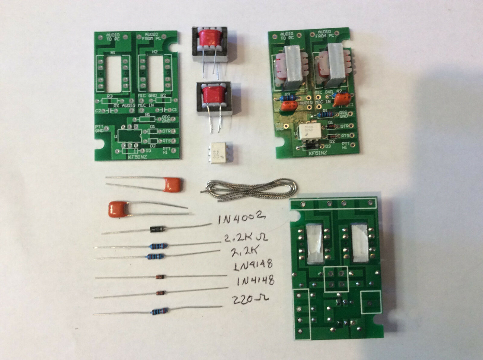
No, we didn’t re-invent the wheel, we just made a convenient, single board, isolated, digital interface that works for almost all of the digital modes on HF and VHF/UHF. Works with DIGIPAN, FLDIGI, MTTY, MMSSTV, JT-65, FT-8, and most all other sound card programs! Work PSK-31, PSK-63, RTTY, SSTV, NBEMS, plus many other modes on your HF or VHF/UHF rig.Nothing new about this technology, it consists of two 600 ohm line transformers for audio input and output from your pc to your transceiver, and an opto-coupled push to talk circuit that works off of an RS-232 port on your computer.
·
Transformer coupled audio eliminates ground loops and AC hum on your signal
·
Opto Coupled push to talk circuit also eliminates ground loops and false triggering of your PTT lines.
·
Very small size, only 2 1/16” x 1 3/8” x .625” high, can be incorporated inside of many radios, with only your RS-232 cable coming outside of the radio.
·
Weighs less than 3 ounces
·
High quality FR-4, solder masked, silk screened Printed Circuit Board
·
Compatible with most modern ham radio transceivers.
These interfaces have been tested on many Kenwood , Icom, Yeasu, and other brand radios.
Simply assemble and hook up per the enclosed wiring diagram and load your software, configure your com port, turn on the radio and have fun on your favorite digital mode!
ITEMS INCLUDED IN YOUR KIT. PLEASE INVENTORY YOUR KIT.
1N4001 DIODE
1 ea
1N4148A DIODE
2 ea
2.2K 1/4W RESISTOR
2 ea
430 OHM 1/4W RESISTOR
1 ea
4N25 OPTO COUPLER
1 ea
.1UFD CAPACITOR
2 ea
600:600 AUDIO TRANSFORMERS
2 ea
PCB
1 ea
Solder
12”
It is assumed that you have a 25 – 45 watt soldering iron. Pencil type tips are preferred. Use of a soldering GUN is NOT recommended due to the small sizes of the solder pads and small spacing between pads. You will also need a pair of wire cutters and a pair of needle nose pliers. The 12” of solder supplied should be enough to solder several of these boards – use the solder sparingly – to end up with a professional looking and operating board with no solder shorts. This board should take approximately 15 minutes to assemble and solder.
1.)
Using the printed circuit board layout, find the locations for the two 1N4148A Diodes and install them.
Observe the polarity. The band on the diode must be oriented to the band on the circuit board layout.
Bend the leads so that the diodes lay flat on the circuit board.
Solder and clip the leads off close to the board.
2.)
Find the locations for the two 2.2k 1/4W Resistors and install them.
Bend the leads so that the resistors lay flat on the circuit board.
Solder and clip the leads off close to the board.
3.)
Find the location for the 430 ohm 1/4W Resistor and install it.
Bend the leads so that the resistor lays flat on the circuit board.
Solder and clip the leads off close to the board.
4.)
Find the location
for the 1N4001 Diode and install it.
Observe the polarity.
The band on the diode must be oriented to the band on the circuit board layout.
Bend the leads so that the diode lays flat on the circuit board.
Solder and clip the leads off close to the board.
5.)
Find the location for the 4N25 optocoupler IC, and install it.
Pin1 of the opto-coupler is indicated by a small circular indentation in the top left corner of the IC.
Orient pin 1 of the opto-coupler to the
pin1 location on the circuit board.
The leads of the opto-coupler will need to be bent inward a slight amount to fit into the circuit board.
After installing the 4N25 optocoupler IC, solder the 6 leads.
6.)
Find the location for the two .1ufd capacitors and install them.
The capacitors are NOT polarized, so they can be installed either direction.
Push the capacitors down close to the board but do not force them completely down or you will break the body of the capacitor.
Solder and clip the leads off close to the board.
7.)
Find the locations for the two 600 ohm to 600 ohm transformers.
Install the transformers in the three centermost holes on both sides of the transformer.
Push the transformers down flat against the board and solder the 6 leads of each transformer.
8.)
If you use the supplied solder, you do NOT have to clean the circuit board after soldering.
9.)
REVIEW:
a.
Recheck steps 1 thru 7 above to insure that you have installed the correct parts in the correct locations on the circuit board.
b.
Inspect each and every solder joint to insure there are no solder shorts and that every lead is soldered.
c.
Insure that all leads have been clipped and that there are no pieces of wires or other debris causing shorts on the circuit board.
10.)
Wrap-up:
a.
Your board is now complete and ready to be connected to your radio and computer per the enclosed installation drawing.
b. ENJOY the digital modes!
Please review our feedback - we've sold over 350 of these little guys with great acceptance by all who have purchased. Units have been sold to U.S.A., United Kingdom, Canada, Australia, France, Italy, and Brazil.
A NOTE ABOUT CUSTOMS FEES - for our offshore customers, customs fees are something we can not control. We declare actual value on customs forms and list it as "Amateur Radio Apparatus". Customs fees are your responsibility.
No, we didn’t re-invent the wheel, we just made a convenient, single board, isolated, digital interface that works for almost all of the digital modes on HF and VHF/UHF. Works with DIGIPAN, FLDIGI, MTTY, MMSSTV and most all other sound card programs! Work PSK-31, PSK-63, RTTY, SSTV, NBEMS, plus many other modes on your HF or VHF/UHF rig. Please note that the RTTY mode is RTTY(AFSK) as produced by MTTY software.
This interface will NOT directly drive any type of printer, it simply interfaces your radio to your computer with isolation. All operating modes need to be sound card based.
Nothing new about this technology, it consists of two 600 ohm line transformers for audio input and output from your pc to your transceiver, and an opto-coupled push to talk circuit that works off of an RS-232 port on your computer.
Transformer coupled audio eliminates ground loops and AC hum on your signal
Opto Coupled push to talk circuit also eliminates ground loops and false triggering of your PTT lines.
Very small size, only 2 1/16” x 1 3/8” x .625” high, can be incorporated inside of many radios, with only your RS-232 cable coming outside of the radio.
Weighs less than 3 ounces
High quality FR-4 single sided, solder masked, silk screened Printed Circuit Board
Compatible with most modern ham radio transceivers.
These interfaces have been tested on the following radios:
Kenwood:
TM-271,
TM-621, TM721A, TR-7400, TR-7850, TR-7950, TS-120, TS-130, TS-440, TS-450,
TS-480SAT, TS-530, TS-820S, TS-870, TS-930, TS-50
ICOM:
IC-208H, IC-706, IC706MKIIG,
IC-746 PRO, IC-781, IC-2100H, IC-2200H, IC-2820H
YAESU: FT-817, ft-747, FT-857, FT-2800M, FT-2000
ALNICO DX-77
COBRA 145GTL-DX (10 METER RADIO)
ELCRAFT K2
QUANSHENG TG-UV2
Baofeng UV-5R etc.
and others. If your radio is not listed here, you probably can use this interface with it. Please send us an email and tell us what radio you want to use. We will respond within 24 - 48 hours.
Simply hook up per the enclosed wiring diagram and load your software, configure your com port, turn on the radio and have fun on your favorite digital mode!
Priced at .95, a value that’s hard to beat.
Since we do not have any control over how you wire this unit to your radio, returns are accepted, however, please email us with any problems you may encounter.
If you return it and we find that it has been abused or modified in such a way as to render it unusable we will NOT refund your purchase price.
We are not responsible for wiring errors or damage to your equipment should you wire it up wrong.
We will be glad to help you work through installation.
Unit comes with schematic wiring diagram and instructions.
Please do not leave negative feedback before contacting us for help on your installation.
We have 14 of these interfaces installed among Charro Radio Club members and all work very well.
Here is some recent EBAY feedback:
Excellent board, fair price, prompt shipping. I am QRV PSK31, etc. 73!
Works well, easy set up.
works great
Perfect A+ 5min to set up and brilliant results :)
Item as described, prompt shipment, would use this seller again.
GREAT SOUND ADAPTER! THANKS!
very neat and well built, arrived within 5 days of order...brilliant service!!
A+ Dealer, Shipped Fast, Good Communications, Would Buy Again, YOU should 2
item as listed, well made, would use again.
Great seller and product! Highly recommended!
Interface works well, very fast shipping, thank you!
excellent product-surprised at how small it was
Perfect for digital modes, many thanks A+++++
Neat little item works great
Very fast delivery, well packed, excellent sound card I/F, many thanks.
I got EXACTLY what I needed, SUPERFAST delivery.. what more could one ask for?!?
ANOTHER UNIT ON THE AIR... NO PROBLEMS FROM BOX TO ON AIR 10 MINUTES
Best deal anywhere on sound card interface works very well no issues tnx n3gty
Working well no issues mounted in my project box on air in 30 after open pkg
Customer email:
"Well you might have to put me on a commission. The interfaces are far better Than MFJ products or the Signallink units.
I get on our local digital net and I get great reports on data quality, so I let everyone know what I am using As an interface and
you get another unit shipped."
Please see our "OTHER ITEMS" for a full selection of Easy Digi interface modules!


